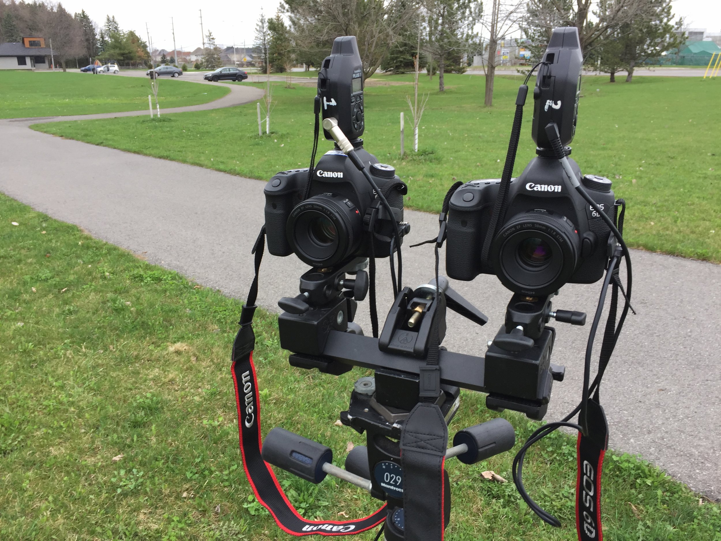
Fig. 1. Stereoscopic Rig #01 (Source: Machinski, 2018).
The process of photographing the images simultaneously using two separate cameras for the stereoscopic images was a challenge. Using a cable releases was difficult to time the camera to fire at the same time and wireless remotes not reliable, as infrared remotes don’t perform well in daylight due to sunlight’s high infrared content. Radio slaves as remote triggers were used, Pocket Wizards, the signal could not be co-opted by natural impediments and if any interference did occur a change in channel easily remedied the situation.
Fig 2. Stereoscopic Rig #02 (Source:Machinski, 2018)
My first rig, made out of a Manfrotto tripod crossbar, did not yield repeatable results as the round tube did not easily allow me to level the pitch of both cameras equally, see Figure 1 Stereoscopic Rig #01.
Fig 3. Measuring (Source: Machinski, 2018).
My second rig I used a square crossbar which had the effect of self-levelling the pitch of the camera, as the Manfortto super-clamp used to position the camera and tripod had a square opening within the inner clamp, this made it easy to setup as it was self-levelling. For this rig I set the distance between the two cameras using the 1:30 Rule, which is a ratio between the base and the distance to the subject of 1/30 (Curtain, D.P., 2011). The distance of my subject would be 20 feet, I decided on this based on the 50mm lenses I wanted to use to get an approximate 3/4 shot of a person. Using this calculation I set the distance between the two cameras to 8 inches to achieve the desired three-dimensional effect when viewing the final stereoscope. Setting the distance of the cameras based on this calculaton created an Orthostereo effect, the scene appears at a normal size and distance (Curtain, D.P., 2011).
Fig. 4. Becoming Wilderness VIII (Source: Lindergård, 2013)
Another issue was making sure both cameras were set to the exact same settings, the white balance of the images were set using a colour meter along with colour compensating filtration. Even though the settings were exactly the same there were slight difference in the colour of the images and adjustments needed to be made in Photoshop.
I liked the results of the stereoscopic process and I like the intimacy the viewer gets when viewing the images, you are literally immersed in the image as you have to bring the viewer to your eye. However, I was concerned about showing the images, you can not view them as three dimensional online, in a gallery setting stereo viewers would have to used for each image. Two photographers Inka & Niclas Lindergård have use this process to document landscapes and have displayed their work in galleries using stereoscopic viewers mounted to the walk, see Fig. 4. Becoming Wilderness VIII. This would be fairly costly to produce so for me it is a little cost prohibited.
Also the process of taking the images is very rigid, if you adjust the subject distance the cameras have to be moved. The rigidity of photographing with two cameras for the stereoscopic process is well suited for stationary objects and landscapes, like Inka & Niclas Lindergård work. Another option would be purchase a stereoscopic camera but this is also cost prohibitive. After discussing the process with my Practice 1: Art and Design tutor I was encouraged to look at other processes something I will be pursuing.
Images
Fig. 5. Test Image Rig #01 (Source: Machinski, 2018)
As I was not employing the 1:30 Rule the images did not line up making the three dimensional effect difficult to view.
Fig. 6. Test Image 02 Rig #02 (Source: Machinski, 2018)
The replacement square crossbar worked well and focusing 20 feet created a three dimensional effect with the image aligning in the stereo viewer.
Fig. 7. Test Image 03 Rig #02 (Source: Machinski, 2018)
Once again the replacement crossbar worked well, having something in the foreground of the image enhances the three dimensional effect.
Fig. 6. Test Image 03 Rig #02 (Source: Machinski, 2018)
All camera setting identical including white balance and colour compensation filter using a colour meter, however, a slight colour shift occurs between the two images.
Stereoscopic Resources
Curtain, D.P. (2011) A Short Course BookStereo Photography 3D in the Digital Era Available at: http://www.shortcourses.com/stereo/stereo3-14.html [Accessed: 28 May, 2018].
National Stereoscopic Association (2018) NSA Stereographic Resources Program. Available at: https://www.stereoworld.org/nsa-stereo-lists/ [Accessed: 28 May, 2018].
Spicer S. (2008) Digital Photography and Ortho-stereo. Available at: http://www.44bx.com/stereo/orthostereo.pdf [Accessed: 25 May, 2018].
The London Stereoscopic Company (2008) How To Take Stereo Photographs. Available at: http://www.londonstereo.com/stereophotography2.html [Accessed: 24 May, 2018].
wikihow How to Create Stereo Photographs. Available at: https://m.wikihow.com/Create-Stereo-Photographs [Accessed: 21 May, 2018].
Citations
Curtain, D.P. (2011) A Short Course BookStereo Photography 3D in the Digital Era Available at: http://www.shortcourses.com/stereo/stereo3-14.html [Accessed: 28 May, 2018].
Lindergård I. & Lindergård, N (2013) Becoming Wilderness VII [photograph] Available at: http://inkaandniclas.com/#/becoming-wilderness-2/16 [Accessed: 26 April, 2018].
Machinski, J. (2018) Photograph of Holmes Stereo Viewer. June 2018. Unpublished.
Machinski, J. (2018) Stereoscopic Rig #01. May 2018. Unpublished.
Machinski, J. (2018) Measuring. May 2018. Unpublished.
Machinski, J. (2018) Stereoscopic Rig #02. May 2018. Unpublished.
Machinski, J. (2018) Test Image Rig #01. May 2018. Unpublished.
Machinski, J. (2018) Test Image 02 Rig #02. May 2018. Unpublished.
Machinski, J. (2018) Test Image 03 Rig #02. May 2018. Unpublished.
Machinski, J. (2018) Test Image 04 Rig #02. May 2018. Unpublished.


